This matters most to the people responsible for keeping these systems running: facilities managers in hospitals, engineers overseeing school and university campuses, chief engineers in office towers, and plant engineers in manufacturing environments. When a chiller underperforms, knowing whether the problem originates on the evaporator side or the condenser side is the difference between a targeted fix and an expensive guessing game.
This article explains how each component functions, how they connect within the refrigeration cycle, what degrades their performance, and which operational signals should be on your monitoring list.
Key Takeaways
- The evaporator absorbs heat from building or process water; the condenser rejects that heat to air or water outside the system
- Both sit on opposite sides of the refrigeration cycle: evaporator on the low-pressure side, condenser on the high-pressure side
- DOE data shows dirty evaporator and condenser tubes can increase compressor energy consumption by up to 30%
- Tube sheet condition — corrosion, erosion, joint integrity — directly governs heat transfer efficiency in both components
- Tracking the right performance indicators for each component lets you catch degradation early — before it forces a shutdown
What Are the Evaporator and Condenser in a Chiller?
Both are heat exchangers, but they serve opposite roles in the same refrigeration circuit.
The Evaporator
The evaporator sits between the expansion valve and the compressor, on the low-pressure side of the system. Low-pressure liquid refrigerant enters and absorbs heat from the returning warm chilled water. As heat transfers across the tube wall, the refrigerant boils into a low-pressure vapor. The now-cooled water exits and circulates to air handling units throughout the building.
In short: heat moves from the water into the refrigerant. The water gets colder. The refrigerant gets hotter.
The Condenser
The condenser sits between the compressor and the expansion valve, on the high-pressure side. High-pressure, high-temperature refrigerant vapor enters and releases heat to the cooling medium — either outdoor air (air-cooled) or condenser water routed through a cooling tower (water-cooled). The refrigerant cools and condenses back into a high-pressure liquid, ready to repeat the cycle.
In short: heat moves from the refrigerant out to the environment. The refrigerant gets colder. The cooling medium gets warmer.
Why the Distinction Matters
Confusing evaporator with condenser problems leads directly to misdiagnosis. Both conditions can look like "the chiller isn't cooling properly" — but the corrective actions are different:
- High chilled water supply temperature → evaporator-side issue
- Elevated head pressure or rising compressor amperage → condenser-side issue
Regardless of construction type — shell-and-tube or brazed-plate — the fundamental heat transfer roles remain the same across commercial chiller designs.
How the Refrigeration Cycle Connects the Evaporator and Condenser
The refrigeration cycle is a closed loop. Refrigerant circulates continuously, alternately absorbing and releasing heat. The evaporator and condenser are the two points where that heat exchange actually happens; the compressor and expansion valve drive the pressure changes that make it possible.
Evaporation — Heat Absorption at the Evaporator
Low-pressure liquid refrigerant enters the evaporator. Because pressure is low, the refrigerant's boiling point is well below the temperature of the returning chilled water. Heat flows from the warmer water across the tube wall into the cooler refrigerant. The refrigerant boils and exits as low-pressure vapor. The chilled water, now cooled to setpoint, circulates to air handlers throughout the building.
Compression — Moving Between Components
The compressor draws the low-pressure vapor from the evaporator and raises it to high pressure and temperature. This pressure increase is what allows the refrigerant to release heat on the other side — the condenser medium (air or water) needs to be cooler than the condensing refrigerant for heat to flow outward.
Condensation — Heat Rejection at the Condenser
High-pressure, high-temperature refrigerant vapor enters the condenser. It releases heat to the cooling medium — outdoor air via fans in air-cooled units, or condenser water routed to a cooling tower in water-cooled units. As the refrigerant cools below its condensing point, it converts back to high-pressure liquid and discharges that collected heat from the system.
Expansion — Resetting for the Next Cycle
The high-pressure liquid passes through the expansion valve, which drops its pressure and temperature sharply. This returns the refrigerant to the low-pressure, low-temperature state needed to absorb heat again in the evaporator, completing the loop.
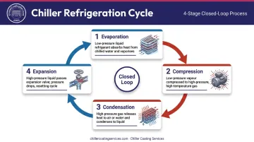
Each stage depends on the one before it. When corrosion degrades the tube sheets or water boxes at either the evaporator or condenser, heat transfer efficiency drops across the entire cycle — which is why the condition of these surfaces matters as much as the mechanical components driving the refrigerant through them.
Evaporator vs. Condenser: Key Functional Differences
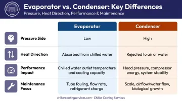
These functional differences determine how facilities teams read monitoring data, diagnose performance losses, and prioritize maintenance — so it's worth understanding each role clearly.
Heat Transfer Direction
This is fixed, regardless of chiller type or operating conditions:
- Evaporator: Heat flows into the refrigerant from the process fluid (heat absorption)
- Condenser: Heat flows out of the refrigerant to the rejection medium (heat discharge)
Pressure Levels
| Component | Pressure Side | Effect |
|---|---|---|
| Evaporator | Low pressure | Enables refrigerant to boil at lower temperatures, absorbing heat from chilled water |
| Condenser | High pressure | Raises refrigerant condensing temperature above the rejection medium so heat flows outward |
Downstream System Impact
Evaporator performance directly affects:
- Chilled water outlet temperature
- Cooling capacity delivered to air handlers and served spaces
Condenser performance directly affects:
- Compressor head pressure
- Energy consumption
- System pressure stability
That last point carries real cost implications. According to the DOE, raising condensing temperature from 95°F to 105°F reduces cooling capacity by 7% — and that's before accounting for the added compressor workload. The energy penalty compounds quickly when condenser heat rejection degrades.
Maintenance Focus
For the evaporator, maintenance centers on preserving heat absorption capacity:
- Clean tube surfaces (fouling directly reduces heat transfer coefficient)
- Adequate chilled water flow rate
- Proper refrigerant charge
For the condenser, maintenance centers on sustaining heat rejection capacity:
- Clean coil or tube surfaces
- Unobstructed airflow (air-cooled) or adequate condenser water flow (water-cooled)
- Water treatment to prevent scale and biological growth
Key Factors That Affect Evaporator and Condenser Performance
Evaporator Performance Factors
- Chilled water flow rate — inadequate flow reduces heat transfer and raises approach temperature
- Entering water temperature — water entering too warm pushes the system toward capacity limits
- Refrigerant charge level — undercharge limits evaporator flooding and reduces capacity
- Tube surface condition — fouling, scale, or biofilm on tube walls insulates against heat transfer; Trane's diagnostic guidance identifies a normal evaporator approach of 1–2°F for non-glycol systems and recommends tube cleaning when approach exceeds 5°F
Condenser Performance Factors
- Ambient air temperature (air-cooled) or condenser water supply temperature (water-cooled)
- Airflow or water flow rate through the heat exchanger
- Scale and mineral deposits — Trane data shows just 0.6 mm of condenser tube scale reduces heat-transfer efficiency by 34% and increases energy consumption by 21%
- Biological growth — biofilm accelerates pitting and further degrades heat transfer
Both sets of performance factors converge at one shared component: the tube sheet.
Tube Sheet Condition — Both Components
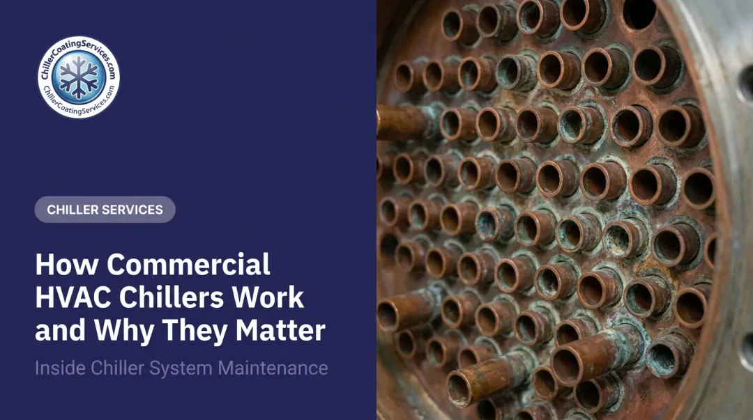
The tube sheet secures individual tubes and directs fluid through the heat exchanger. On both the evaporator and condenser side, it faces corrosion stressors that compound over time:
- Galvanic corrosion at dissimilar metal junctions (copper tubes against steel or cast iron tube sheets)
- Pitting from dissolved oxygen, aggressive water chemistry, and biofilm
- Erosion and cavitation damage at inlet-side tube ends from high-velocity water entry
- Crevice corrosion in the tight annular gap at tube-to-tube-sheet joints
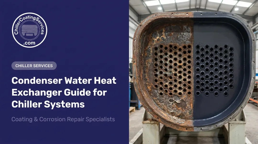
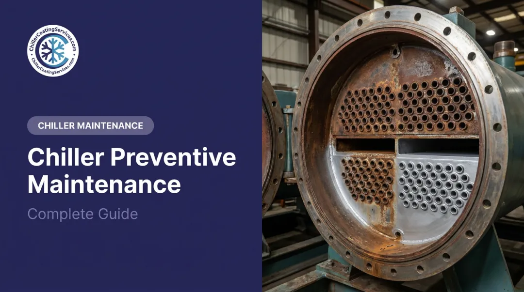
When tube-to-tube-sheet joint integrity degrades, the consequences go beyond efficiency loss. Refrigerant-to-water cross-contamination becomes a real risk, and corrosion damage can allow fluid bypass that directly undermines heat transfer on either side. Addressing tube sheet condition through protective coatings or restoration is one of the most effective ways to maintain performance across both heat exchangers.
Common Issues and Maintenance Considerations
The Most Common Misconception
Most facilities assume chiller performance problems originate at the compressor. In practice, the majority of efficiency losses trace back to degraded heat transfer in the evaporator or condenser — fouling, scale buildup, and corrosion on internal surfaces rather than mechanical compressor failure.
Compressors fail, but they're often pushed to failure by chronic heat exchanger degradation on one or both sides. Addressing the heat exchangers first is both the more cost-effective and more accurate diagnostic path.
What Neglected Surfaces Actually Cost
Mineral scale, biological fouling, and corrosion pitting on evaporator and condenser tubes reduce the rate of heat transfer, forcing the compressor to work harder. The DOE's 30% energy penalty figure for dirty tubes reflects real operating conditions in facilities where tube maintenance has been deferred.
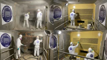
Physical deterioration at the tube sheet — pitting, joint loosening, inlet erosion — compounds the efficiency problem and introduces structural risk. Proactive surface protection addresses corrosion before it reaches that point. Chiller Coating Services uses a three-step process: deep cleaning, contained abrasive blasting to a white metal SSPC-SP 5 / NACE No. 1 finish, and a 100% solids protective coating application. The result is a non-conductive barrier that stops galvanic corrosion, resists pitting and erosion, and in documented cases increases tube-to-tube-sheet joint push-out strength by over 1,000 pounds.
Operational Indicators to Monitor
Evaporator-side signals:
- Rising chilled water supply temperature relative to setpoint
- Elevated evaporator approach (leaving water temperature minus saturated refrigerant temperature exceeding 5°F)
- Poor cooling response in served spaces
Condenser-side signals:
- Rising head pressure trends
- Increased compressor amperage draw
- System high-pressure trip events
- Elevated condensing temperature relative to ambient or condenser water conditions
Both sets of indicators belong in a routine preventive maintenance program. Tracking them as trends — not just responding to alarms — is what separates facilities that catch problems early from those that deal with unplanned outages.
Frequently Asked Questions
What is the difference between evaporator and condenser in a chiller?
The evaporator absorbs heat from the chilled water loop (low-pressure, cooling side), causing refrigerant to boil from liquid to vapor. The condenser rejects that collected heat to the outside environment via air or water (high-pressure, discharge side), condensing the refrigerant back to liquid. They are functionally opposite but interdependent components in the same continuous cycle.
What is an evaporator in a chiller?
The evaporator is the heat exchanger on the low-pressure side of the system — between the expansion valve and compressor — where liquid refrigerant absorbs heat from returning warm chilled water and boils into vapor. The now-cooled water then circulates to air handling units throughout the building or facility.
What are the 4 parts of a chiller?
The four core components are the evaporator (absorbs heat from chilled water), compressor (raises refrigerant pressure and temperature), condenser (rejects heat to air or water), and expansion valve (drops refrigerant pressure, resetting conditions for the evaporator).
What causes poor heat transfer in a chiller evaporator or condenser?
The most common causes include:
- Fouling and scale buildup on tube surfaces, which act as insulating barriers against heat transfer
- Reduced fluid flow (water or air) through the heat exchanger
- Physical deterioration such as corrosion, pitting, or cavitation damage at tube sheets and tube walls
How does tube sheet condition affect chiller evaporator and condenser performance?
The tube sheet secures individual tubes and directs fluid flow through the heat exchanger. When the tube sheet surface corrodes, erodes, or allows tube joint failure, it compromises the seal between fluid circuits, introduces contamination risk, reduces thermal conductivity, and can cause refrigerant leakage. Both evaporator and condenser performance degrade when tube sheet integrity is compromised.