The problem is that most damage starts quietly. Fouling, corrosion, and tube sheet deterioration build gradually until performance drops enough to trigger an alert — by which point repair scope and cost have already grown significantly. According to the U.S. Department of Energy's Operations & Maintenance Best Practices Guide, preventive maintenance saves 12% to 18% compared with reactive maintenance — a meaningful gap that compounds over the life of the equipment.
This guide covers the most common causes of heat exchanger damage, warning signs to act on, repair and refurbishing methods, how to decide between repair and replacement, and a practical maintenance schedule.
Key Takeaways
- Fouling, corrosion, erosion, and mechanical fatigue are the leading causes of heat exchanger degradation — all manageable with proactive maintenance
- Declining heat transfer output, rising energy costs, and visible corrosion are the clearest early warning signs
- Tube sheet coating is a high-impact refurbishing step that prevents corrosion recurrence and extends service life
- Repair and refurbishing typically cost far less than replacement when damage is caught early and the core structure is sound
- Annual professional inspections are the baseline — aggressive or high-demand environments need more frequent checks
Common Causes of Heat Exchanger Damage
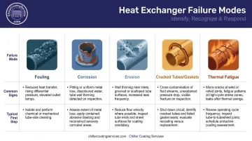
Heat exchangers fail in predictable ways — and knowing which failure mode is active determines whether cleaning, coating, or component replacement is the right call.
Fouling
Scale, rust, biological matter, and process deposits accumulate on heat transfer surfaces, acting as insulation. A peer-reviewed HVAC&R Research study of cooling-tower brazed-plate condensers found that severe fouling caused up to a 28% heat-flux reduction and a 250% pressure-drop increase under aggressive water chemistry conditions. The system works harder, draws more energy, and loses capacity — all without any visible external sign.
Corrosion
Chemical reactions between process fluids and metal components attack tube sheets, water boxes, and tube ends over time. Galvanic corrosion is particularly problematic at tube-to-tube-sheet joints, where dissimilar metals in contact with water create an electrolytic cell.
According to Faes et al. (2019) in Corrosion Reviews, galvanic corrosion at tube-baffle and tube-sheet contacts is a common failure mode in shell-and-tube heat exchangers when different metals are used. Left unaddressed, it causes pitting, joint deterioration, and eventual tube-to-tube-sheet leaks.
Erosion
High-velocity fluids — particularly those carrying abrasive particles — wear away internal surfaces at tube entrances, U-bends, and inlet zones. EPRI operating experience documents inlet-side tube inner-diameter erosion from high water velocity. Once wall thinning begins at these hotspots, rupture risk increases with each operating cycle.
Leaks from Cracked Tubes or Failed Gaskets
Cracked tubes, pinhole failures, and worn gaskets allow cross-contamination between fluid circuits. In chiller systems, this means water migrating into the refrigerant side — triggering capacity loss, refrigerant contamination, and potential regulatory exposure in sensitive environments like hospitals or pharmaceutical facilities.
Mechanical Stress and Thermal Fatigue
Repeated heating and cooling cycles create cumulative metal fatigue through differential expansion and contraction. Systems that run continuously or experience frequent start/stop cycles are especially vulnerable. Cracks from thermal fatigue will keep recurring unless the root cause — the cycling pattern or operating condition driving them — is identified and corrected.
Each of these failure modes calls for a different intervention. The table below maps each cause to its most common indicators and typical repair pathway:
| Failure Mode | Common Signs | Typical First Step |
|---|---|---|
| Fouling | Reduced flow, rising energy draw | Chemical cleaning or mechanical descaling |
| Corrosion | Pitting, joint discoloration, leaks | Surface prep + protective coating |
| Erosion | Wall thinning at inlets, U-bends | Velocity reduction, inlet coating |
| Cracked tubes / failed gaskets | Cross-contamination, fluid loss | Tube plugging, gasket replacement |
| Thermal fatigue | Recurring surface cracks | Operating cycle review + coating |
Warning Signs Your Heat Exchanger Needs Repair or Refurbishing
Catching these signals early significantly reduces repair scope and cost. Each of the following should prompt an inspection — not a wait-and-see response.
Performance and Efficiency Changes
Declining heat transfer output is one of the clearest early indicators. Watch for:
- Outlet temperatures drifting outside expected ranges
- Longer cycle times to reach set points
- Rising condenser approach temperature
- Increased kW/ton without added load
Rising energy consumption points to the same problem. When a system draws more power to maintain the same output, blocked heat transfer surfaces or degraded internals are forcing the equipment to overcompensate. Even 0.6 mm of fouling on condenser water tubes can reduce chiller efficiency by approximately 20% — a figure that shows how quickly minor buildup becomes a real operating cost.
Visible Damage, Corrosion, or Leaks
During visual inspections, look for:
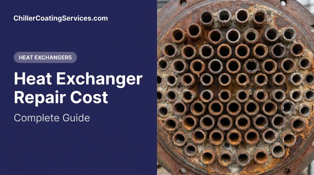
- Rust streaking or mineral deposits on tube sheets and inlet areas
- Pitting or discoloration on accessible water box surfaces
- Coolant puddles or staining around connections and nozzles
- Discoloration suggesting localized overheating
Tube-to-tube-sheet joint deterioration deserves specific attention. Corrosion or erosion at these joints leads directly to cross-contamination between fluid circuits. Once joints fail, repair scope escalates significantly.
Abnormal System Behavior
- Unexpected pressure drops across the exchanger often indicate internal blockages, partial tube failures, or significant fouling buildup
- Abnormal temperature differentials between inlet and outlet suggest reduced heat transfer effectiveness
- Recurring shutdowns or manual resets signal that the unit can no longer maintain stable operation under normal conditions — cumulative degradation rather than a one-off fault
When multiple warning signs appear together, the window for lower-cost intervention narrows quickly. An inspection at this stage is far less disruptive than emergency repairs after a failure.
Heat Exchanger Repair and Refurbishing Methods
Restoration is not one-size-fits-all. The right approach depends on damage type, exchanger design, and how much downtime the facility can absorb.
Cleaning and Fouling Removal
Cleaning is the most frequently needed intervention and often the fastest path to restoring efficiency.
Common cleaning approaches:
- Mechanical brushing — effective for moderate tube-side fouling in accessible tube bundles
- High-pressure water jetting — removes hard scale and heavy deposits where brushing is insufficient; verify tube material compatibility before use
- Chemical circulation (CIP) — circulates a cleaning solution through the system without full disassembly; well-suited for plate heat exchangers and chemically soluble deposits
Clean-in-Place (CIP) deserves a note: Alfa Laval's guidance confirms that CIP can restore heat transfer efficiency before complete fouling sets in, without requiring disassembly. For facilities where downtime is constrained, it's the least disruptive maintenance option. HVAC chiller case reviews found that online automatic tube cleaning produced at least a 24.5% electrical energy reduction following installation — though that figure reflects a specific mechanical cleaning system, not a universal guarantee.
Component Repair: Tubes, Gaskets, and Plates
Three repair interventions cover most component-level failures:
- Tube plugging and retubing — plugging isolates a failed tube at the tube sheet using welded or mechanical attachment (per ASME PCC-2); widespread bundle degradation warrants full retubing to extend service life without replacing the shell or frame
- Gasket replacement — gaskets degrade from pressure and temperature cycling; re-gasketing proactively when multiple gaskets fail in a short window avoids the cost of repeated reactive replacements
- Welding and brazing — cracked metallic components in shell-and-tube exchangers can be repaired by welding or brazing, followed by post-weld hydrostatic pressure testing before the unit returns to service
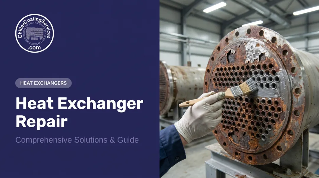
Tube Sheet Coating and Protective Surface Treatment
Tube sheet coating is one of the highest-value steps in any refurbishing project — yet it's frequently overlooked until corrosion has already progressed.
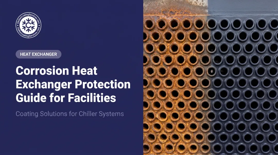
Why tube sheets are particularly vulnerable: The tube sheet sits at the convergence of dissimilar metals, high-velocity water flow, dissolved oxygen, and chemical treatment agents. Pitting, galvanic corrosion, crevice attack, and erosion all concentrate at tube inlet zones, where turbulence is highest.
Without protection, that degradation continues throughout the equipment's service life.
What professional tube sheet coating involves:
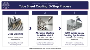
A rigorous coating process follows a disciplined sequence:
- Deep cleaning — removes biofilm, scale, corrosion deposits, and contaminants that would mask underlying damage or prevent coating adhesion
- Contained abrasive blasting to white metal finish — blast surfaces to SSPC-SP 5 / NACE No. 1 standard, producing a contaminant-free, high-profile surface for maximum coating adhesion; severely corroded areas are reconstructed to restore metal thickness before coating is applied
- 100% solids protective coating application — a zero-VOC, non-shrinking epoxy system covers tube sheet faces, tube ends, and water box interiors
The choice of a 100% solids formulation matters. Unlike solvent-based coatings that contain only 50–80% solids and shrink during cure, a 100% solids system delivers maximum film build per coat with no solvent flash-off. The result is a denser, structurally stronger cured film suited for constant water-side immersion.
What this coating system delivers:
- A non-conductive barrier that eliminates the electrolytic pathway between dissimilar metals, stopping galvanic corrosion at the joint
- Protection against pitting, crevice corrosion, erosion, and cavitation damage
- Tube-to-tube-sheet joint reinforcement, with documented push-out strength gains of over 1,000 pounds in some cases — directly addressing joints weakened by prior corrosion
- Smoother surfaces that reduce fouling accumulation and improve heat-transfer efficiency
- Quick-cure technology that minimizes operational downtime during the service window
Chiller Coating Services applies this three-step process to shell-and-tube, plate, and brazed-plate heat exchangers across facilities in Massachusetts, New Hampshire, Connecticut, Rhode Island, Maine, Vermont, and New York — with scheduled mobilization during planned outage windows and emergency response capability for unplanned corrosion discoveries.
Full Unit Refurbishing
Full refurbishment encompasses frame inspection, tube bundle evaluation, re-gasketing, external sandblasting and repainting, and hydrostatic pressure testing before return to service. It's the right call when multiple systems are degraded simultaneously, when the unit's value justifies the investment, or when the goal is to reset the service life clock for another full operational cycle. For facilities requiring frame-level structural work alongside coating restoration, full refurbishment and coating scopes are typically coordinated as complementary services.
Repair vs. Refurbish vs. Replace: How to Decide
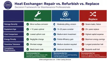
The right decision depends on more than the lowest upfront quote.
Factors That Determine the Right Path
| Factor | What to Evaluate |
|---|---|
| Damage severity | Is damage localized (tubes, gaskets, tube sheet surface) or structural? |
| Equipment age | How far into the expected service life is the unit? |
| Cost comparison | Repair + coating vs. replacement cost, including lead times |
| Energy penalty | What is the ongoing efficiency loss costing in energy spend? |
| Downtime tolerance | Can the facility absorb extended outage for full replacement? |
| Compliance requirements | Does the repaired unit meet current safety or regulatory standards? |
When Repair or Refurbishing Wins
Targeted repair combined with protective coating is typically the stronger financial choice when:
- Damage is localized to tubes, gaskets, or tube sheet surfaces
- The unit is mid-life with a structurally sound shell and frame
- The corrosion mechanism (galvanic, pitting) can be stopped with a non-conductive coating
- Lead times for new equipment would create longer downtime than repair
Protective coatings applied during refurbishment are particularly effective at extending equipment life. By interrupting galvanic and electrolytic attack at tube-to-tube-sheet joints — where corrosion typically originates — a properly executed coating project can add years of reliable service without the cost or lead time of full replacement.
When Replacement Is the Only Practical Option
Some damage scenarios are beyond what repair can address cost-effectively. Replacement becomes necessary when:
- Structural damage spans multiple components beyond economical repair
- Tube bundle integrity is compromised to the point where cross-contamination has already occurred
- The unit uses obsolete specifications with no available parts
- Repeated failures have made cumulative repair costs approach or exceed replacement cost
- Safety or compliance requirements cannot be met by a repaired unit
Heat Exchanger Maintenance and Inspection Schedule
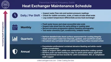
Maintenance frequency must be calibrated to the operating environment. A hospital chiller running 24/7 in a chemically demanding environment needs more frequent attention than a light-commercial unit running seasonally.
| Frequency | Tasks |
|---|---|
| Daily / Per Shift | Check fluid levels; log temperature and pressure readings; scan for visible leaks or unusual sounds |
| Monthly | Assess fouling indicators (approach temperature, pressure drop trend); inspect connections and accessible gaskets; clean as needed |
| Quarterly | Inspect tube sheet condition and accessible water box surfaces; check for corrosion or pitting; benchmark flow performance against baseline |
| Annual | Professional inspection; pressure drop analysis; tube plugging assessment; coating condition evaluation; full cleaning; consider tube sheet coating maintenance if corrosion indicators are present |
High-usage or chemically aggressive environments — pharma, food processing, power plants, and facilities using aggressive anti-scale treatments — should shorten the intervals above. Annual professional inspections remain the minimum. Semi-annual or quarterly checks are warranted where run hours are high, water chemistry is aggressive, or prior corrosion history indicates elevated risk.
For regulatory context, ANSI/ASHRAE/ACCA Standard 180 establishes the minimum inspection and maintenance requirements for commercial HVAC systems. Treat it as the floor, not the ceiling, for critical or high-demand applications.
Frequently Asked Questions
Can a heat exchanger be cleaned?
Yes — and it should be cleaned regularly. Methods range from chemical clean-in-place (CIP) circulation to mechanical brushing and high-pressure water jetting, depending on fouling type and severity. Many cleaning approaches restore heat transfer efficiency without requiring full disassembly.
Is it worth replacing a cracked heat exchanger?
It depends on crack location, extent, and equipment age. Small, localized cracks in a mid-life unit are often repairable through welding and protective coating, with post-repair pressure testing to verify the repair. Extensive cracking across an aging unit typically makes full replacement the more economical long-term decision.
What are the most common causes of heat exchanger failure?
The most common culprits are fouling, galvanic corrosion at tube-to-tube-sheet joints, erosion from high-velocity fluids, gasket degradation, and thermal fatigue from repeated heating and cooling cycles. These mechanisms tend to compound each other — fouling accelerates corrosion, which in turn weakens joints already stressed by cycling.
How long does heat exchanger repair typically take?
Scope determines duration. Basic cleaning takes hours; tube plugging, re-gasketing, or tube sheet coating with quick-cure technology can be completed within a planned maintenance window with minimal downtime. Full refurbishment or retubing may require several days depending on unit size and damage extent.
When should a heat exchanger be refurbished instead of replaced?
Refurbishing is the better choice when the core structure is sound but surface components — tubes, gaskets, tube sheet surfaces, or coatings — are degraded. Combined with protective tube sheet coating, refurbishing can restore full performance and extend service life for significantly less than the cost of full replacement.
How often should a heat exchanger be professionally inspected?
Annual professional inspections are the baseline for most commercial and industrial applications. Facilities with continuous operation, aggressive water chemistry, or prior corrosion history should move to semi-annual or quarterly intervals. Between scheduled inspections, tracking pressure drop, approach temperature, and energy consumption trends enables early detection before issues escalate.