Introduction
Selecting the right shell and tube heat exchanger is one of the most consequential decisions a facilities engineer makes — one that shapes energy costs, system uptime, maintenance budgets, and equipment service life for years to come. Get it wrong, and you're looking at accelerated fouling, galvanic corrosion at tube-to-tube-sheet joints, and unplanned outages that dwarf the original equipment cost.
According to Market Research Future, shell and tube exchangers represent approximately 65% of the global heat exchanger market — a dominance earned by their flexibility across pressure ranges, temperatures, and fluid types. This guide covers what they are, how each component functions, and the critical design and selection factors that determine whether a specified unit performs as intended.
Key Takeaways
- Shell and tube exchangers transfer heat between two fluids through tube walls — the standard workhorse of industrial heat transfer
- Configuration choice (fixed tube sheet, U-tube, floating head) determines maintainability and thermal expansion handling
- Fluid allocation — which fluid runs tube-side vs. shell-side — is the most critical early design decision
- TEMA Classes R, C, and B set design rigor; the wrong class means overbuilt costs or premature failure
- Tube sheet protection from corrosion, fouling, and galvanic attack is what determines long-term service life
What Is a Shell and Tube Heat Exchanger?
As Thermopedia defines it, a shell and tube heat exchanger is an indirect-contact device consisting of a tube bundle mounted inside a cylindrical shell. One fluid flows through the tube interiors; the other flows over the outside of the tubes within the shell. Heat transfers through the tube walls. The two fluids never mix.
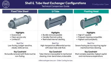
The Three Primary Configurations
| Configuration | Best For | Key Constraint |
|---|---|---|
| Fixed tube sheet | Clean services, small temperature differentials | Shell-side surfaces not mechanically accessible; thermal stress at high ΔT |
| U-tube | Handles thermal expansion; bundle removal possible | U-bends make internal tube cleaning difficult |
| Floating head | High temperature differentials, frequent cleaning | More expensive and mechanically complex |
The configuration decision is primarily about maintainability and thermal expansion, not first cost. Fixed tube sheet designs are the most economical but require clean shell-side service and a limited temperature differential.
U-tube designs allow bundle removal and handle thermal cycling well, but internal tube cleaning is restricted by the bend geometry. Floating head designs add cost and complexity — use them when large temperature differentials and frequent mechanical cleaning are both requirements.
Why Shell and Tube Designs Dominate Heavy Industry
- Wide pressure and temperature tolerance
- Material flexibility (carbon steel, stainless, titanium, Inconel, copper alloys)
- Accessible for cleaning and repair
- Scalable across a broad range of heat duty requirements
Core Components of a Shell and Tube Heat Exchanger
Each component shapes both thermal performance and long-term reliability — and knowing where vulnerabilities develop helps you catch problems before they become failures.
Shell
The shell is the outer pressure-containing vessel. For diameters up to 610 mm (24 inches), standard pipe is typically used; larger shells are fabricated from rolled and welded plate. Select shell material based on operating pressure, temperature, and the corrosiveness of the shell-side fluid.
At the inlet nozzle, an impingement plate protects the tube bundle from fluid-induced erosion and vibration. Per TEMA guidance, impingement protection is required when the momentum parameter (ρV²) exceeds 2,230 kg/m·s² for non-corrosive single-phase fluids.
Tubes and Tube Bundle
Tubes are the primary heat transfer surface — and their specification drives both thermal performance and maintainability. Key parameters:
- Common ODs: 5/8", 3/4", and 1"
- Standard lengths: 6, 8, 12, 16, 20, and 24 feet
- Wall thickness: Specified by BWG (Birmingham Wire Gauge) rating
- Pitch patterns: Triangular (higher tube density, better heat transfer) vs. square (required for mechanical shell-side cleaning)
- Materials: Carbon steel, stainless steel, titanium, Inconel, copper alloys — matched to corrosion resistance and conductivity requirements
TEMA minimum tube pitch is 1.25 × tube OD. Tighter spacing weakens the tube sheet ligament and risks joint leakage during rolling.
Tube Sheet
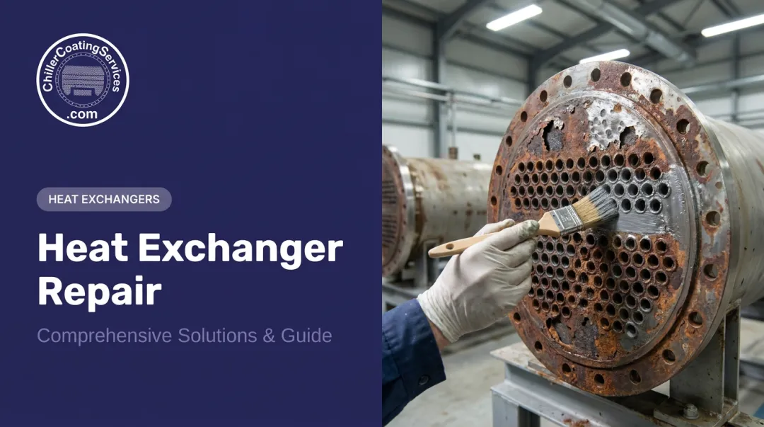
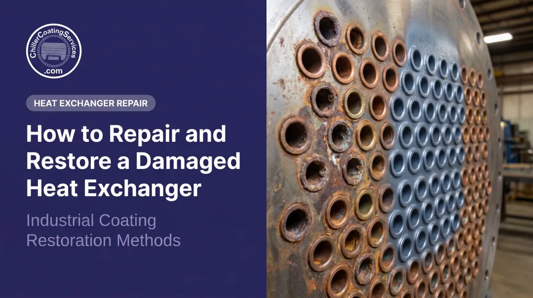
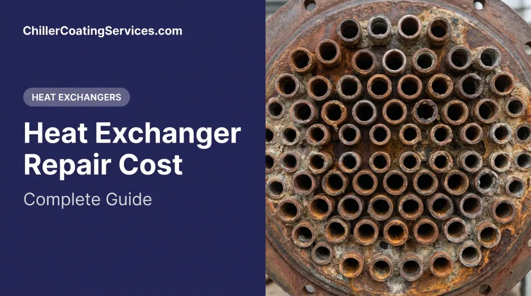
The tube sheet is a thick metal plate drilled with precisely positioned holes. Tube ends insert into these holes and are secured by welding or mechanical/hydraulic expansion, creating the seal that keeps shell-side and tube-side fluids from mixing.
Tube sheets are the most corrosion-vulnerable component in the exchanger. Three factors concentrate risk here:
- Simultaneous exposure to both process fluids
- The tube-to-tube-sheet joint is a documented leak point under thermal cycling
- Dissimilar metals at the junction create conditions for galvanic attack
In HVAC and chiller applications, this joint is where failures most commonly originate.
Baffles
Segmental baffles do more than direct flow — they're structural. Their three functions:
- Support tubes against vibration and sagging
- Maintain tube spacing
- Direct shell-side fluid across the tube bundle in a serpentine path to maximize turbulence and heat transfer
Baffle cut — measured as a percentage of shell diameter — is typically 20–25% for effective heat transfer. Baffle cut and baffle spacing together control shell-side velocity, pressure drop, and heat transfer coefficient. Wider spacing reduces pressure drop but also reduces turbulence and lowers the heat transfer rate.
Channels and Heads
Channels (front and rear heads) direct tube-side fluid into and out of the tube bundle. The head type determines both cleaning access and pass configuration:
- Bonnet-type heads suit services that don't require frequent tube-side cleaning access
- Removable cover heads allow inspection without disturbing connected piping
- Pass partition plates inside the channels create multi-pass arrangements that increase tube-side velocity and heat transfer
TEMA's three-letter designation identifies the front head type, shell type, and rear head type — capturing the full mechanical configuration in a single shorthand reference. A BEM, for example, specifies a bonnet front head, single-pass shell, and fixed rear head. An AES uses a removable cover front head with a floating rear head for easier bundle removal.
Key Design and Selection Considerations
Optimizing a shell and tube exchanger for a specific application means balancing thermal performance targets, mechanical constraints, fluid properties, and total lifecycle cost. Each factor below connects directly to measurable operational outcomes.
Fluid Allocation: Tube Side vs. Shell Side
The most important early design decision is fluid assignment. Engineering guidance on fluid allocation establishes these governing rules:
| Fluid Characteristic | Preferred Side | Reason |
|---|---|---|
| High pressure | Tube side | Pressure containment is more economical in smaller-diameter tubes |
| Corrosive or toxic | Tube side | Specialty materials limited to tubes and related parts only |
| Dirty, fouling, solids-bearing | Tube side | Easier mechanical cleaning access |
| Highly viscous or low HTC | Shell side | Baffles increase turbulence more effectively on shell side |
| Phase-change service | Shell side | Larger flow area handles vapor with lower pressure drop |
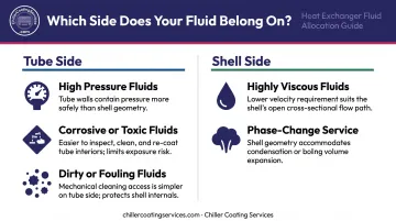
Fluid allocation is a first-principles decision. Material selection, cleaning access, pressure rating, and fouling management all follow from it — misassigning a fluid at this stage compounds through every downstream design choice.
Material Selection and Galvanic Corrosion Risk
Tube and shell materials must satisfy thermal conductivity, corrosion resistance, operating temperature and pH compatibility, and mechanical strength under thermal cycling — all at once.
A 2019 review published in Corrosion Reviews documented galvanic corrosion at tube-to-tube-sheet contacts when dissimilar metals are used. One case involved copper tubes with a carbon steel tube sheet, causing fluid cross-contamination within four months.
The risk extends beyond individual component selection. Galvanic compatibility must be evaluated at every metal interface: tubes, tube sheet, baffles, water boxes, and gaskets.
Common pairings in practice:
- Carbon steel shell / stainless steel tubes — general industrial and HVAC service
- Carbon steel shell / titanium tubes — aggressive water chemistry or corrosive process fluids
- Carbon steel shell / copper alloy tubes — legacy commercial HVAC (highest galvanic risk at tube sheet)
Where dissimilar metals are unavoidable, the tube-to-tube-sheet joint interface requires protective treatment to interrupt the galvanic circuit.
Operating Pressure, Temperature, and Configuration Selection
Pressure and temperature limits define the mechanical design class and directly influence shell thickness, tube wall gauge, flange ratings, and material grades. No single universal pressure/temperature range covers all shell and tube exchangers. Final design is always code-driven, governed by ASME BPVC Section VIII Division 1 for pressure vessel construction and, for petroleum and petrochemical service, API 660.
Large temperature differentials between the two fluids create thermal stress, particularly at the tube-to-tube-sheet joint in fixed tube sheet designs. When differential expansion is a concern, the configuration decision shifts toward U-tube or floating head designs, or an expansion joint is incorporated into the shell.
TEMA Class and Standards Compliance
TEMA's three mechanical classes set the design rigor baseline:
- Class R — Severe petroleum refinery and heavy process service. Most rigorous dimensional and material requirements.
- Class B — Chemical process service. Intermediate between commercial and heavy petroleum.
- Class C — General commercial and light industrial. Appropriate for many HVAC and institutional applications.
Specifying the wrong TEMA class directly affects project cost. Class R equipment in a light commercial application means unnecessary expense. Class C equipment in a high-severity process application means premature failure.
All shell and tube exchangers functioning as pressure vessels must also comply with ASME BPVC Section VIII. Petroleum, petrochemical, and natural gas applications add API 660 requirements covering material selection, fabrication, inspection, and testing.
Fouling Factors and Velocity Management
Fouling — scale deposits, biological growth, corrosion byproducts, particulate settling — is among the most common causes of reduced heat transfer and increased pressure drop over time. A refinery preheat train study found that without intervention, fouling-driven throughput loss reached 21,000–306,000 tonnes over three years, representing $0.8M–$11.3M in lost opportunity for that case alone.
Design velocity targets exist precisely to manage this risk:
- Tube-side liquid: 1–2 m/s typical; up to 4 m/s where fouling reduction justifies the pressure drop
- Shell-side liquid: 0.3–1 m/s
- Atmospheric gas: 10–30 m/s
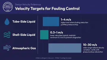
Velocities too low allow solids to settle and biofilm to establish. Velocities too high cause erosion, tube vibration, and joint damage. Fouling factors (dirt coefficients) must be included in the overall heat transfer coefficient calculation at design time. That calculation sets a baseline, but actual fouling rates depend on water chemistry, operating cycles, and maintenance intervals — all of which require ongoing monitoring to stay ahead of performance losses.
Pressure Drop Limits
Higher velocities that suppress fouling also drive up pressure drop, which is why allowable pressure drop is a binding design constraint — not a secondary consideration. For low-viscosity liquids, typical design targets are 35–70 kN/m² (~5–10 psi). For gas and vapor services, limits vary by system pressure:
- High vacuum: 0.4–0.8 kN/m²
- Medium vacuum: ~0.1 × absolute pressure
- 1–2 bar gauge: ~0.5 × system gauge pressure
Pressure drop and heat transfer pull in opposite directions — tighter baffle spacing, more tube passes, and higher velocities all improve heat transfer but increase pressure drop. Final design requires balancing both against pumping energy cost and operational cost targets. Exceeding pressure drop limits also risks flow-induced vibration damage to the tube bundle.
How Chiller Coating Services Can Help Protect Your Heat Exchanger
Proper design and material selection set the foundation. But long-term performance of a shell and tube heat exchanger (particularly in chiller, HVAC, and industrial cooling applications) depends on protecting the tube sheet and tube-to-tube-sheet joints from corrosion, erosion, and galvanic attack across decades of service.
Chiller Coating Services, headquartered in Franklin, NH, brings over 40 years of management team experience to this problem. The company serves hospitals, power plants, manufacturing facilities, universities, data centers, and commercial buildings across New England and New York — facilities where water-side corrosion and fouling conditions degrade tube sheets over time.
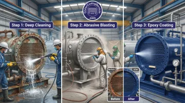
The three-step service process:
- Deep cleaning : removes biofilm, scale, corrosion deposits, and contaminants to expose the true metal condition
- Contained abrasive blasting to white metal finish : equivalent to SSPC-SP 5 / NACE No. 1, the highest standard in industrial surface preparation; severely corroded areas are reconstructed before coating is applied
- 100% solids epoxy coating application : applied to tube sheets, tube ends, and water box interiors at 10 mils dry film thickness
What the coating system delivers:
- Galvanic corrosion prevention — the non-conductive cured epoxy interrupts the electrolytic pathway between dissimilar metals at the tube-to-tube-sheet junction
- Push-out strength — coating application has demonstrated joint push-out strength gains of over 1,000 pounds in some cases, directly reinforcing a known failure point
- Fouling reduction — smooth, dense coating surfaces resist scale and biofilm adhesion, maintaining heat transfer performance over time
- Chemical and immersion resistance — formulated to withstand long-term immersion and resist the acidic anti-scale treatments common in chiller water circuits
- Minimal downtime — quick-cure technology and single-mobilization service design minimize operational disruption
The service is available across MA, NH, CT, RI, ME, VT, and NY. Chiller Coating Services also provides documented service records supporting Joint Commission/CMS healthcare audits, ISO/FDA/GMP industrial compliance, NERC utility regulatory documentation, and SOC 2 data center audit support.
Conclusion
Selecting and designing the right shell and tube heat exchanger means connecting fluid properties, pressure and temperature demands, material compatibility, TEMA class requirements, and fouling management into a complete specification. Every trade-off at design time — configuration type, fluid allocation, material pairing, baffle geometry — has direct consequences for operating cost and equipment longevity.
Heat exchanger performance isn't static. In the field, three failure modes consistently cut service life short:
- Fouling buildup on tube surfaces that reduces heat transfer efficiency over time
- Corrosion at dissimilar-metal interfaces, particularly where tube ends meet tube sheets
- Tube-to-tube-sheet joint degradation from repeated thermal cycling
Periodic inspection and proactive maintenance address the first two. For tube sheet and tube end corrosion specifically, professional protective coating — applied after abrasive blasting to a white metal finish — stops active corrosion, rebuilds corroded areas, and adds a non-conductive barrier that prevents galvanic attack. Facilities that treat coating as part of the maintenance program, not an afterthought, consistently extend equipment service life and avoid the cost of premature bundle replacement.
Frequently Asked Questions
What is a shell and tube heat exchanger used for?
Shell and tube exchangers handle process heat recovery in refineries and chemical plants, cooling of hydraulic fluid and lubricating oil in industrial equipment, steam condensing in power generation, and evaporator/condenser service in commercial and institutional HVAC chiller systems. Their pressure and temperature range flexibility makes them the default choice across most heavy industrial heat transfer applications.
How long do shell and tube heat exchangers last?
Service life depends on design quality, material selection, operating conditions, and maintenance practices — no single universal benchmark applies. The most common causes of premature failure are tube sheet corrosion from galvanic attack, fouling buildup, and tube-to-tube-sheet joint deterioration. Protective coatings and regular inspection extend operational life beyond what uncoated, unmaintained equipment achieves.
What is the 10/13 rule for shell and tube heat exchangers?
In heat exchanger engineering, the 10/13 ratio is a fluid-side pressure heuristic used in tube-rupture scenario analysis — specifically, comparing the low-pressure side design pressure against 10/13 of the high-pressure side design pressure. It is not a tube pitch rule. The correct tube layout standard is TEMA's minimum tube pitch requirement: 1.25 × tube OD, which ensures sufficient ligament strength between holes for proper tube rolling without leakage risk.
What is the difference between the shell side and tube side in a heat exchanger?
The tube side carries fluid through the interior of the tubes; the shell side carries fluid around the outside within the shell. Assignment is determined by pressure (high pressure goes tube-side), corrosiveness, fouling tendency (fouling fluids go tube-side for easier cleaning), and viscosity (viscous fluids benefit from shell-side baffles that add turbulence).
How often should a shell and tube heat exchanger be inspected?
Under API 510 pressure vessel programs, internal inspection intervals are the lesser of 10 years or half of estimated remaining life. SMRP guidance recommends external visual inspection at least every five years. Priority areas include tube sheet condition, tube wall thickness, and joint integrity — where degradation most often causes capacity loss.
What causes fouling in shell and tube heat exchangers?
Fouling results from mineral scale, biological growth, particulate settling, corrosion byproducts, and chemical reactions at tube surfaces. Inadequate fluid velocity, poor water treatment, and dissimilar-metal corrosion accelerate buildup. Left unaddressed, fouling increases thermal resistance, raises pressure drop, and progressively degrades performance between cleaning cycles.