Over time, predictable failures emerge: fouling reduces heat transfer efficiency, tubes corrode and leak, pressure drops climb, and thermal stress cracks what repeated cycling has weakened. Left unaddressed, these issues compound — driving up energy costs, forcing unplanned shutdowns, and ultimately pushing facilities toward premature equipment replacement.
This guide covers the five most common shell and tube heat exchanger failures, a step-by-step troubleshooting process, the repair-versus-replace decision, and the preventive measures that extend service life significantly.
Key Takeaways
- The five most common failures are fouling, tube leaks, tube sheet corrosion, high pressure drop, and flow-induced vibration
- Confirming root cause before acting prevents repeat failures and wasted repair costs
- Temperature differentials and pressure readings together used together narrow the diagnosis faster than either reading alone
- Tube sheet corrosion and joint leaks are frequently repairable through surface restoration — full replacement is often unnecessary
- Scheduled preventive maintenance consistently costs less than emergency repairs or unplanned chiller downtime
Common Problems With Shell and Tube Heat Exchangers
Most failures follow predictable patterns tied to fluid quality, operating conditions, and maintenance history. Recognizing them by symptom prevents misdiagnosis.
Fouling and Reduced Heat Transfer
Symptoms: Gradual rise in outlet temperatures, reduced thermal efficiency, higher energy consumption than baseline.
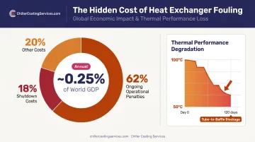
Likely cause: Mineral scale, sediment, biological growth, or process deposits accumulating on tube surfaces. These deposits act as insulation, reducing the effective heat transfer coefficient. A 2019 peer-reviewed modeling study found that shell-side fouling reduced hot-fluid temperature decrease from over 100°C to just 50°C, with tube-to-baffle clearances fully blocked after 120 days.
The financial impact compounds quickly. Industry analysis estimates fouling costs at approximately 0.25% of world GDP, with 62% attributed to ongoing operational penalties and 18% to shutdown costs alone.
Tube and Tube-to-Tube Sheet Leaks
Symptoms: Fluid contamination between shell-side and tube-side streams, visible drips at tube sheet faces or end caps, unexplained pressure loss.
Likely cause: Corrosion or erosion at tube walls or tube-to-tube sheet joints, degraded gaskets, improper service during maintenance (wrong gasket type, incorrect torque), or mechanical stress from thermal cycling. Peer-reviewed failure analysis has documented cases where 45% of 1,500 tubes in a single bundle failed due to cracks originating at tube surfaces and welded tube-to-tube sheet regions.
Tube Sheet Corrosion
Symptoms: Pitting or discoloration at tube sheet faces, leaks near tube entry points, loss of tube-to-tube sheet joint integrity, fluid cross-contamination.
Likely cause: Galvanic corrosion from dissimilar metal contact between tubes and tube sheet, aggressive process fluids, absence of protective coatings, or prolonged immersion without corrosion inhibitors. Crevice corrosion forming in the gap between tube external surfaces and the tube sheet is a documented primary failure mode — one case study identified chloride anions, formic acid, H₂S, and CO₂ as the primary corrosive agents in a natural gas treating plant exchanger.
When left uncoated, tube sheet surfaces are among the first components to fail — and the resulting fluid cross-contamination can shut down an entire chiller system.
High Pressure Drop
Symptoms: Increased pump energy consumption, flow rate below design spec, visible fouling or scale when the unit is opened.
Likely cause: Internal blockages from fouling or debris, partially closed isolation valves, undersized upstream piping, or tube deformation restricting flow paths. Shell-side design pressure drops are often constrained to 10–15 psi in engineering practice — sustained readings above that range warrant immediate investigation.
Flow-Induced Vibration and Thermal Stress Cracking
Symptoms: Audible rattling or humming during operation, visible tube wear at baffle contact points, cracks near welds or tube ends after rapid temperature changes.
Likely cause (vibration): Shell-side fluid velocity exceeding design limits causes tube bundle vibration against baffles. According to peer-reviewed literature, fluidelastic instability is the most severe vibration mechanism and can cause tube failure within hours. Longer-term fretting from turbulence-induced buffeting causes progressive tube-wall thinning.
Likely cause (thermal stress): Abrupt startup/shutdown cycles or mismatched thermal expansion between shell and tube materials drive stress cracking near welds and tube ends. Systems without gradual ramp-up procedures are most at risk.
How to Troubleshoot and Fix a Shell and Tube Heat Exchanger
Applying a fix before confirming the root cause is the single most common troubleshooting error. Replacing a heat exchanger due to elevated temperatures, for example, won't solve a problem caused by upstream flow restriction or poor cooling water quality.
Step 1: Identify the Exact Problem
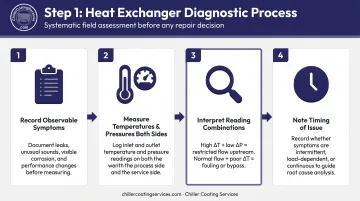
- Record all observable symptoms: leaks, temperature deviations, abnormal pressures, vibration, noise, or fluid discoloration
- Measure and document entering and leaving temperatures and pressures on both shell side and tube side
- High temperature differential with low pressure drop points to restricted flow upstream
- Normal flow with poor temperature change indicates fouling or an internal bypass condition
- Note when the issue occurs — startup, peak load, continuously, or after recent maintenance — as timing often narrows the root cause category
Step 2: Confirm the Root Cause Before Acting
The data gathered in Step 1 should point toward one of four root cause categories:
- Mechanical: tube failure or compromised tube-to-tube sheet joints
- Chemical/environmental: corrosion, scaling, or biological growth
- Operational: flow imbalance or incorrect fluid velocity
- Maintenance-related: inadequate cleaning or incorrect gasket installation
Rule out external factors first. Verify that cooling water supply temperature, flow rate, and pressure are within design specs before opening the unit. Many apparent heat exchanger failures are actually upstream system problems.
Step 3: Apply the Correct Fix Based on Root Cause
Once the root cause is confirmed, the repair approach should match it directly. Applying the wrong fix wastes downtime and often leaves the underlying problem intact.
For fouling:
- Perform chemical cleaning (circulate appropriate descaling or biocide solution), mechanical tube brushing, or high-pressure water jetting
- Hydroblasting typically operates at 10,000 psi / 70 MPa or above for effective deposit removal
- Choose cleaning method based on chemical analysis of the deposit type
- Schedule cleaning before fouling becomes compacted; well-run programs typically achieve an energy-savings-to-cleaning-cost ratio of 3:1 or better
For tube leaks and failed tube-to-tube sheet joints:
- Inspect all tube ends with dye penetrant or eddy current testing to locate compromised tubes
- Per ASME PCC-2 guidance, inspect a minimum of 10% of tubes for bundles over 1,000 tubes, or 50 tubes / 25% for bundles under 500 tubes
- Plug failed tubes as a short-term measure; re-roll or re-seal tube-to-tube sheet joints where integrity has been lost
- For tube sheet surface degradation, professional surface restoration using a 100% solids epoxy coating can rebuild integrity and add a non-conductive barrier that prevents galvanic corrosion. Chiller Coating Services performs this type of restoration for industrial and commercial facilities across New England and New York.
For corrosion:
- Identify the corrosion type (galvanic, crevice, pitting) and adjust fluid chemistry with appropriate inhibitors
- Replace corroded tubes with material compatible with the process fluid
- Apply protective coatings to tube sheet surfaces as both a corrective and preventive measure — a 100% solids non-conductive coating eliminates the electrolytic pathway between dissimilar metals, directly stopping galvanic corrosion at its source
For high pressure drop:
- Inspect and clear blocked strainers upstream
- Clean tube-side and shell-side passages
- Verify valve positions and piping sizing
- Replace deformed or collapsed tubes obstructing flow
Step 4: Test and Validate the Fix
- Restart under normal operating conditions and allow the unit to reach thermal equilibrium before recording data
- Compare entering and leaving temperatures and pressures against pre-failure baseline or design specifications
- Monitor for recurrence over a minimum of one full operating cycle or 30 days
- If the same symptom returns, escalate to a more thorough internal inspection or NDT assessment
When to Repair vs. Replace a Shell and Tube Heat Exchanger
The repair-or-replace decision comes down to three factors: how widespread the damage is, how much remaining service life the unit has, and whether repair costs justify the outcome relative to a new unit.
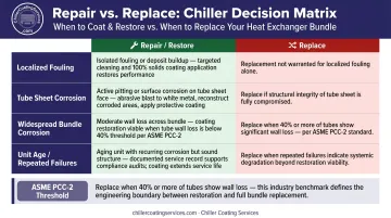
A commonly referenced industry data point from ASME PCC-2 is that total bundle replacement is recommended when inspected tubes show wall loss of 40% or more — a concrete threshold for the most severe deterioration scenarios.
| Scenario | Repair | Replace |
|---|---|---|
| Localized fouling or single-tube failure | Clean or plug and continue; rarely justifies replacement | Only if fouling recurs at unusually short intervals |
| Tube sheet surface damage or galvanic corrosion | Professional surface restoration — often far less expensive than replacement | When structural integrity cannot be restored |
| Widespread tube bundle corrosion | Partial retubing if shell and tube sheets remain sound | When more than 40% of tubes show significant wall loss |
| Unit age and repeated failures | Targeted repairs if within design life | Beyond design life or when process changes exceed original design envelope |
Tube sheet restoration is often the most cost-effective path when surface damage or galvanic corrosion is present. Professional restoration using a 100% solids epoxy coating system can rebuild tube sheet integrity, improve push-out strength at tube joints by over 1,000 pounds in some cases, and add durable corrosion resistance.
Chiller Coating Services performs this work in three steps: deep cleaning, contained abrasive blasting to a white metal finish (SSPC-SP 5 / NACE No. 1 equivalent), and 100% solids coating application. Technicians reconstruct severely corroded areas before applying the coating, because applying over compromised metal leads to premature failure. For facilities across New England and New York, this process routinely delivers a reliable alternative to full unit replacement.
Common Mistakes to Avoid When Troubleshooting
Four mistakes account for a disproportionate share of repeat failures and post-maintenance callbacks:
- Chase root cause, not symptoms. Replacing a heat exchanger because of high outlet temperatures — without first measuring supply water flow and temperature — leads to the same failure recurring. Use pressure and temperature data together to locate where the problem originates in the system.
- Validate every repair before returning to service. Restarting without comparing readings to baseline leaves it unclear whether the fix worked. Undetected issues re-emerge quietly and typically cause more serious damage the second time.
- Verify gasket specifications before reinstalling. Gaskets that look identical may carry different chemical or temperature resistance ratings. Wrong gasket selection after service is one of the most frequent causes of post-maintenance leaks. Always check the spec against the manufacturer's documentation.
- Manage water chemistry per exchanger, not per system. A treatment program effective elsewhere in a cooling loop may accelerate scaling in a shell and tube exchanger running at higher temperatures. High temperature, elevated chloride content, and low pH each promote pitting corrosion in stainless steel components. Water chemistry management must account for the specific operating conditions of each unit.
Preventive Maintenance to Avoid Future Issues
Reactive troubleshooting is always more expensive than scheduled prevention. Direct cleaning costs for a single heat exchanger typically run $700–$1,000, while a single failure event can reach $1.5 million in studied industrial models. That cost gap makes the case for consistent preventive programs clear.
Core preventive actions:
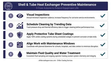
- Conduct visual inspections at defined intervals — minimum annually, more frequently for units in corrosive service or handling high-mineral-content water; check tube sheet faces, gaskets, and external surfaces for early pitting, staining, or joint weeping
- Schedule cleaning before performance data shows degradation — tracking pressure drop and thermal efficiency over time allows trending that predicts when cleaning is needed, rather than reacting after measurable efficiency loss has already occurred
- Apply protective tube sheet coatings proactively during scheduled outages — 100% solids coating systems reduce fouling, prevent galvanic corrosion, and improve joint push-out strength with minimal downtime impact
- Align coating work with your facility's natural maintenance windows — summer break for schools, shoulder seasons for hospitals, N+1-aware sequencing for data centers
- Maintain fluid quality through consistent water treatment and regular sampling; train operators on correct startup and shutdown sequences to minimize thermal shock cycles that cause stress cracking over time
Preventive coating work also produces a paper trail that pays dividends at audit time. Chiller Coating Services provides documented service records after each application, formatted to support Joint Commission/CMS requirements for healthcare, ISO/GMP compliance for manufacturing, SOC 2 documentation for data centers, and NERC reliability records for power plants — so the maintenance investment holds up under regulatory scrutiny as well as operational review.
Frequently Asked Questions
How do I tell if a shell and tube heat exchanger is faulty?
Key indicators include a rise in outlet temperatures despite stable operating conditions, unexplained pressure drop increases, visible fluid leaks at tube sheet faces or end connections, and fluid contamination between the two process streams. Any of these warrant immediate inspection.
What is the 10-13 rule for heat exchangers?
The "10/13 rule" is an API 521 pressure relief design reference: it sets shell-side design pressure at 10/13 of tube-side pressure to account for tube-rupture scenarios. It is not a repair-versus-replacement threshold. For that decision, ASME PCC-2 is the applicable standard, recommending bundle replacement when tube wall loss reaches 40% or more.
What is the pressure test for shell and tube heat exchangers?
Pressure testing, typically hydrostatic under ASME Section VIII Division 1, verifies shell and tube integrity after repairs or inspections. Test pressure is generally set at 1.3× MAWP per ASME UG-99. Any pressure drop during the hold period indicates a leak that must be resolved before the unit returns to service.
How often should a shell and tube heat exchanger be inspected?
Annual visual inspections are a practical baseline minimum for most installations. Units handling corrosive fluids, high-mineral-content water, or operating at elevated temperatures warrant more frequent checks. ASME PCC-2 specifies inspection sample sizes by bundle size but does not set a universal calendar interval — actual frequency should be based on service conditions and trending performance data.
Can a shell and tube heat exchanger be repaired instead of replaced?
Many failures — including tube sheet corrosion, localized tube failure, and joint leaks — can be addressed through targeted repair, retubing, or professional surface restoration coatings. Full replacement is generally warranted only when damage is widespread, structural integrity cannot be restored, or the unit has exceeded its design life with recurring failures.
What causes tube sheet corrosion in shell and tube heat exchangers?
The primary causes are galvanic corrosion at tube-to-tube sheet junctions, chemically incompatible process fluids, missing or degraded protective coatings, and prolonged exposure to high-mineral or high-chloride water. Crevice corrosion around tube joints, especially where chloride anions and acidic gases are present, accelerates deterioration in industrial service.