When they underperform, the consequences are immediate: rising condensing pressure, compressor overload, and energy costs that climb with every degree of thermal resistance added by scale or corrosion. When they fail outright, an unplanned chiller outage can cascade into patient care disruptions, lease violations, or IT thermal events.
Yet condenser heat exchangers are among the most neglected components in a chiller plant. Facilities managers frequently discover degraded tube sheets, corroded water boxes, and fouled tubes only during fall maintenance — by which point significant damage has already accumulated.
This guide covers how condenser water heat exchangers work, the designs most commonly used in commercial and industrial chiller systems, the failure modes that degrade them fastest, and the maintenance and protection strategies that extend their service life.
Key Takeaways
- Condenser water heat exchanger efficiency directly determines chiller energy consumption
- Shell and tube designs dominate water-cooled chiller condensers because they handle open-loop condenser water and allow mechanical tube cleaning
- Tube sheet corrosion, fouling, and scaling are the leading causes of condenser heat exchanger degradation
- Routine cleaning, eddy current testing, and tube sheet coatings extend equipment service life
- Proactive protection costs far less than emergency repair or capital replacement of condenser components
What Is a Condenser Water Heat Exchanger in a Chiller System?
A condenser water heat exchanger is the component that removes heat from the high-pressure refrigerant vapor leaving the compressor, allowing the refrigerant to condense back into liquid form and continue the cooling cycle. Without effective heat rejection at this point, the entire refrigeration cycle stalls.
Where It Sits in the Refrigeration Cycle
In a water-cooled chiller, the condenser heat exchanger occupies the position between the compressor outlet and the expansion valve. The evaporator — on the other side of the cycle — absorbs heat from the building's chilled water loop. The condenser's job is the inverse: it rejects that heat plus the work added by the compressor into the condenser water loop.
Two fluid streams move through the condenser at all times:
- Hot refrigerant vapor entering from the compressor, releasing heat as it condenses
- Condenser water absorbing that heat and carrying it away to a cooling tower, river, lake, or closed loop
These two fluids are physically separated — they never mix under normal operating conditions.
Why Condenser Performance Directly Affects Energy Costs
A condenser heat exchanger that can't reject heat efficiently forces the refrigerant to operate at higher condensing pressure, which means the compressor must work harder to push refrigerant against that elevated pressure. According to an Australian government chiller efficiency fact sheet, energy consumption can increase by 1.5–2.5% per degree Celsius of elevated condensing temperature, depending on chiller type.
That penalty adds up fast. Fouling, scaling, and corrosion all degrade heat transfer in the condenser, pushing condensing temperatures higher and driving up energy costs every hour the chiller runs.
How Does a Condenser Water Heat Exchanger Work?
Phase-Change Heat Transfer
The condenser's efficiency advantage comes from phase-change heat transfer. As hot refrigerant vapor enters the shell (in a shell-and-tube design), it releases its latent heat — the energy stored in the vapor state — as it transitions back to liquid. Latent heat transfer moves far more energy per unit of temperature difference than sensible heat transfer alone, which is why condensers are compact relative to the heat loads they handle.
Cooler condenser water flowing through the tubes absorbs this released heat. A counterflow arrangement — where water enters at the opposite end from where refrigerant vapor enters — maximizes the temperature differential along the length of the exchanger, which can increase heat transfer rates by 10–15% compared to a parallel-flow configuration.
The heated condenser water exits and returns to a cooling tower, where it releases heat to the atmosphere before re-entering the condenser.
The Tube Sheet: The Most Vulnerable Point
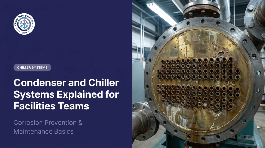
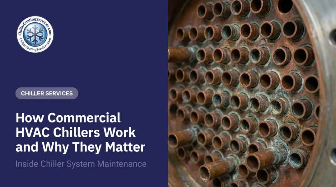
Every tube in a shell-and-tube condenser is anchored at each end in a tube sheet — a structural plate that separates the water side from the refrigerant side. This junction is the most mechanically and corrosively stressed location in the entire heat exchanger.
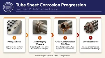
The tube sheet connects dissimilar metals — typically copper alloy tubes meeting a carbon steel shell. In oxygenated, circulating condenser water, this creates an electrolytic pathway for galvanic corrosion. The progression follows a predictable pattern:
- Pitting initiates at the tube-to-tube-sheet joint, where differential oxygen concentration drives metal loss
- Joint integrity weakens as pit depth increases, reducing mechanical pull-out strength
- Cross-contamination risk rises as the barrier between fluid sides degrades
- Structural failure becomes possible if corrosion goes unaddressed through multiple seasons
Performance Indicators to Monitor
Facilities managers should track two key metrics on water-cooled condensers:
- Approach temperature — the difference between the saturated condensing refrigerant temperature and the leaving condenser water temperature. Trane's published benchmarks set the expected range at 1–2°F at full load, with precautionary tube cleaning recommended above 5°F
- Condenser pressure — track trends relative to load and entering water temperature, using the chiller's OEM performance maps as the baseline
One elevated reading means little on its own — flow rate, sensor calibration, and refrigerant charge each affect both metrics. A trend that climbs steadily across multiple readings under comparable load conditions is what confirms heat transfer degradation and warrants investigation.
Types of Condenser Water Heat Exchangers Used in Chillers
Shell and Tube Heat Exchangers
Shell and tube units are the standard choice for water-cooled chiller condensers in commercial and industrial applications. Construction consists of a carbon steel shell housing a tube bundle — typically copper, copper-nickel, stainless steel, or titanium — with tube sheets at each end securing the tubes. Refrigerant circulates in the shell; condenser water flows through the tubes.
Why they dominate condenser service:
- Larger tube passages tolerate the particulate load from open condenser water
- Removable end caps allow mechanical tube brushing or hydroblasting
- Individual leaking tubes can be plugged without replacing the bundle
- Rugged construction handles thermal cycling across seasons
- Available in corrosion-resistant alloys for challenging water chemistry
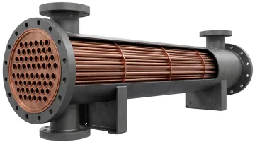
The tradeoffs are physical footprint and higher upfront cost compared to brazed plate alternatives — neither of which outweighs the serviceability advantages in a large building chiller application.
Brazed Plate Heat Exchangers
Brazed plate units stack stainless steel plates brazed with copper-based material, creating alternating thin passages approximately 1/8" wide for refrigerant and water. They're compact and cost-effective — yet those same narrow passages make them vulnerable to fouling from debris and mineral deposits in open-loop condenser water.
Brazed plate condensers are appropriate when:
- The condenser water circuit is a closed loop with clean, treated fluid (glycol or treated water)
- Fine filtration (smaller than 1 mm) is maintained upstream
- Chemical cleaning in place (CIP) is part of the maintenance plan
They are not recommended for direct connection to open condenser water without rigorous upstream filtration.
One important distinction: because internal passages aren't individually accessible for mechanical cleaning, fouling management depends heavily on filtration and backflushing protocols. Manufacturers document chemical cleaning in place (CIP) as a viable maintenance method, but internal mechanical repair isn't an option.
Shell and coil condensers (a tank with an internal water coil) and double-tube condensers see occasional use in smaller or specialty applications. For large commercial and industrial chiller systems, shell and tube construction remains the default.
Common Problems That Degrade Condenser Water Heat Exchanger Performance
Fouling and Scaling
Mineral deposits — calcium carbonate, silica, and similar compounds from condenser water — accumulate on tube interior walls over time, building a layer of thermal resistance between the water and the refrigerant. A DOE/EERE commercial building HVAC report documents a case where automatic tube cleaning reduced the fouling factor from 0.0018 to 0.0002 and cut chiller energy consumption by 17% at one facility.
That's an extreme case, but it illustrates the direction: scale forces the compressor to compensate, and the energy meter reflects every BTU of compromised heat transfer.
Tube Sheet Corrosion and Galvanic Attack
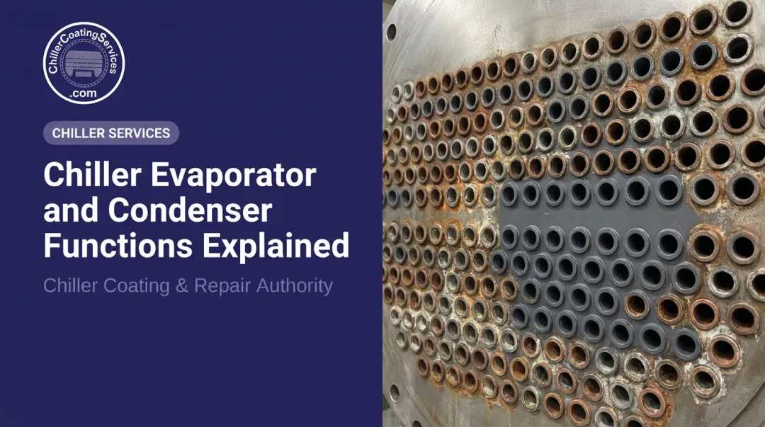
While fouling degrades thermal performance, corrosion threatens the condenser's structural integrity. The tube sheet is where failure starts in most degraded condensers: when copper tubes meet a carbon steel tube sheet in the presence of conductive water, the dissimilar metals form a galvanic cell.
Carbon steel acts as the anode and corrodes preferentially, producing pitting that weakens tube-to-tube-sheet joints, risks refrigerant-water cross-contamination, and compromises the structural integrity of the entire tube bundle.
Galvanic attack accelerates without a protective barrier interrupting the electrolytic pathway. This is the failure mode that tube sheet coatings directly address: a properly applied non-conductive epoxy coating electrically insulates the carbon steel surface, eliminating the galvanic couple between dissimilar metals.
Erosion at Tube Inlets
High-velocity water entering the tubes generates turbulence at the tube sheet face and tube ends. This inlet erosion is a distinct mechanism from chemical corrosion — it's mechanical abrasion from flow dynamics — but it's equally damaging to joint integrity over time.
Cavitation from pressure fluctuations compounds this, creating localized pitting at tube inlets that progressively weakens the tube-to-tube-sheet connection. The three mechanisms often work in combination:
- Fouling builds thermal resistance, forcing the compressor to run harder
- Galvanic corrosion pits and weakens tube-to-tube-sheet joints at the metal interface
- Inlet erosion and cavitation mechanically abrade tube ends and accelerate joint failure
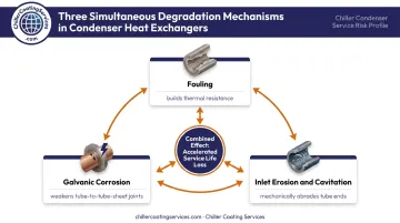
Together, they shorten equipment service life and drive up energy and maintenance costs faster than any single factor alone.
Maintenance and Protection Best Practices
Cleaning and Inspection Protocols
Mechanical tube brushing or hydroblasting removes mineral deposits and biofilm before they become embedded scale. For cooling tower systems, this should occur at least annually — more frequently if water quality monitoring shows elevated mineral content or biological activity.
Beyond cleaning, tube integrity assessment requires nondestructive testing. Eddy current testing identifies wall thinning and defects within tube walls before they cause in-service failure. Trane specifies condenser and evaporator tube testing every three years for certain CenTraVac models, with the interval adjusted based on water conditions and service history.
Establish a baseline inspection log with approach temperature trends, pressure readings, and tube condition findings — that log is what distinguishes proactive maintenance from reactive crisis management.
Water Treatment
Chemical treatment of condenser water controls the three primary degradation pathways simultaneously:
- pH control and corrosion inhibitors slow electrochemical attack on tube and tube sheet metals
- Scale inhibitors prevent mineral deposits from accumulating on tube walls
- Biocides suppress biological fouling and Legionella growth in the condenser water loop
Water treatment and mechanical inspection should be coordinated — what the water chemistry program is doing to the system should inform what inspectors look for during scheduled cleaning windows.
Tube Sheet Coating for Long-Term Protection
Water treatment controls chemistry, but it cannot stop corrosion where dissimilar metals contact each other at the tube-to-tube-sheet junction. A professionally applied tube sheet coating adds a physical barrier that chemical programs alone cannot replicate. It guards against galvanic corrosion, chemical attack, and erosion. The non-conductive epoxy layer also interrupts the electrolytic pathway between dissimilar metals at that junction.
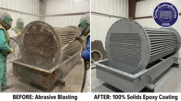
Chiller Coating Services applies a proprietary 100% solids epoxy coating system to condenser tube sheets, tube ends, and water boxes across New England and New York. The process follows three steps:
- Deep cleaning — removal of scale, biofilm, and corrosion deposits to expose the true condition of the metal
- Contained abrasive blasting to white metal finish (SSPC-SP 5 / NACE No. 1 equivalent) — the highest industrial surface preparation standard, ensuring maximum coating adhesion; severely corroded areas are reconstructed before coating is applied
- 100% solids coating application — applied to the tube sheet face, tube ends, and water box; the 100% solids chemistry delivers no solvent flash-off, no shrinkage during cure, and maximum film build per coat
Documented results include tube-to-tube-sheet joint push-out strength increases of over 1,000 pounds in some cases, representing structural reinforcement alongside corrosion protection. The coating also reduces inlet turbulence at tube ends and decreases fouling accumulation on treated surfaces.
Quick-cure technology keeps downtime minimal, with services typically scheduled during planned fall or spring shoulder-season chiller outages.
For facilities in regulated environments — hospitals, data centers, pharmaceutical plants — Chiller Coating Services provides documented service records supporting Joint Commission/CMS, SOC 2, ISO/GMP, and NERC compliance audits.
Frequently Asked Questions
How does a condensing heat exchanger work?
A condensing heat exchanger cools hot refrigerant vapor until it releases its latent heat and transitions from vapor to liquid. That heat transfers to a secondary fluid — water in a water-cooled system, air in an air-cooled system — which carries it away from the chiller.
What is the heat exchanger in a condenser?
The heat exchanger within a condenser is the component — typically a shell and tube or brazed plate unit — that physically separates the refrigerant from the cooling medium while allowing heat to pass between them through the tube walls.
What causes condenser water heat exchanger failure?
The most common causes are tube fouling and scaling from mineral deposits, galvanic corrosion and pitting at the tube sheet, erosion at tube inlets from high-velocity water flow, and undetected tube wall thinning that eventually allows refrigerant-water cross-contamination.
Shell and tube vs. brazed plate condenser heat exchanger: what's the difference?
Shell and tube units are mechanically serviceable, handle open condenser water reliably, and are the standard for large commercial systems. Brazed plate units are compact and lower cost but require clean closed-loop water and chemical cleaning in place — mechanical access isn't an option.
How often should condenser heat exchangers be inspected or cleaned?
Annual mechanical tube cleaning is the baseline for cooling tower systems, combined with year-round water quality monitoring — more frequent cleaning applies where mineral content or water chemistry is aggressive. Plan on eddy current testing of tube walls every three years, adjusted for your specific chiller model and service conditions.