 in Oil Refinery Operations](https://file-host.link/website/chillercoatingservices-mnljm0/assets/blog-images/ce9503c2-1273-49e0-8aa8-48be4497fe4a/1782297471280939_fb361d9e6f8e4e7ebc327d6502539186/360.webp)
Introduction
Oil refineries run on heat. From crude intake to finished product storage, temperature management is constant — and shell and tube heat exchangers (STHEs) are the workhorses making it happen.
Hydrocarbon Processing describes STHEs as used "abundantly throughout the chemical, oil and gas, and fertilizer industries," and for good reason. They handle the extreme pressures, high temperatures, and corrosive process fluids that refinery operations demand — duties that would destroy less robust designs.
The challenge for refinery engineers is threefold: selecting the right exchanger design for each service, choosing materials that resist the specific corrosion threats in each process stream, and maintaining these critical assets without unnecessary downtime. Get any one of those wrong, and the consequences range from reduced efficiency to unplanned shutdowns.
What follows is a practical guide to STHE selection, deployment, degradation, and maintenance — including how protective tube sheet coatings extend service life in even the harshest refinery services.
Key Takeaways
- STHEs handle high pressures, extreme temperatures, and large thermal loads that refinery operations demand
- In refineries, STHEs serve as reboilers, condensers, preheaters, product coolers, and feed/effluent exchangers
- Crude preheat train fouling costs the US refining sector an estimated $1.0–1.2 billion per year
- Fouling, corrosion, and tube sheet degradation are the top causes of reduced efficiency and unplanned downtime
- Tube sheet coatings and disciplined inspection schedules extend STHE service life
How Shell and Tube Heat Exchangers Work in Oil Refineries
The operating principle is straightforward: one fluid flows through a bundle of tubes while a second fluid circulates around those tubes inside an outer shell. Heat transfers through the tube walls — the two fluids never mix. In refinery service, the tube-side fluid is typically the hot or corrosive process stream (crude oil, gas, steam), while cooling water or another process stream runs on the shell side.
Baffles, Flow Configuration, and Multi-Pass Design
Baffles mounted on the shell side force the shell-side fluid to flow across the tube bundle in a cross-flow pattern rather than straight through. This increases turbulence, raises the shell-side heat transfer coefficient, and is especially valuable in refinery streams with varying viscosities or high fouling potential.
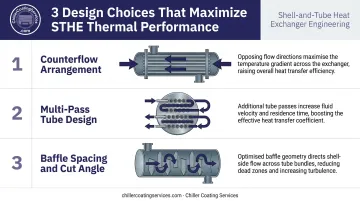
Three design choices work together to maximize thermal performance:
- Counterflow arrangement routes the two fluids in opposite directions, sustaining a larger temperature differential along the full exchanger length — critical for crude preheating and distillate cooling duties
- Multi-pass tube designs (2-pass, 4-pass) route the tube-side fluid back and forth through the bundle multiple times, extending effective contact length and improving heat recovery in crude preheat trains where recovering every BTU counts
- Baffle spacing and cut angle are tuned per service to balance pressure drop against heat transfer, particularly in streams with high fouling potential
Fluid Allocation in Refinery Service
These design decisions directly inform where each fluid is assigned — and that allocation is a deliberate engineering choice, not a default.
Corrosive, high-fouling process streams (crude oil with sulfur compounds, for example) are typically routed through the tube side. Tube interiors are far easier to inspect and mechanically clean than the shell side. Lower-pressure cooling water runs on the shell side, where access for cleaning is less critical.
Key Applications Across Refinery Processes
Crude Preheat Train
Before crude oil enters the atmospheric distillation unit, it passes through a series of STHEs that progressively recover heat from hot product streams leaving the column. According to DOE energy bandwidth data, this preheat train raises crude temperature to approximately 288°C (550°F) before a fired furnace brings it up to the flash zone entry temperature of 343°C–400°C (650°F–750°F).
That heat recovery carries real economic weight. The same DOE analysis puts current atmospheric distillation average energy consumption at 109 × 10³ BTU/bbl against a practical minimum of 50 × 10³ BTU/bbl — a 54% potential energy savings available through improved heat integration, fouling mitigation, and fired-heater efficiency.
Reboilers at Distillation Columns
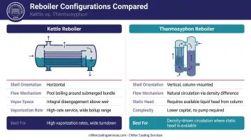
Reboilers supply the heat that drives fractionation. An STHE circulates steam or hot process fluid to vaporize bottom liquids in the distillation column, generating the vapor that separates products. Two configurations dominate:
- Kettle reboilers — horizontal TEMA K-shell design with boiling on the tube bundle exterior, vapor disengagement space above the bundle, and a weir for liquid draw-off. Best suited for high vaporization rates requiring reliable circulation
- Thermosyphon reboilers — use natural circulation driven by the density difference between liquid feed and the two-phase return mixture. Preferred where sufficient static head is available, with vertical units typically mounted close to the column
Overhead Condensers and Product Coolers
At the top of distillation columns, overhead condensers cool and condense hydrocarbon vapors back to liquid products (naphtha, light gasoline) using cooling water on the shell side. These exchangers must handle the full condensate load from the column overhead, making reliable heat transfer critical to product yield.
Product coolers serve a different purpose: finished products (diesel, kerosene, jet fuel, heavy gas oil) must reach safe storage temperatures before entering tanks. Fully welded STHE configurations are often preferred here, reducing maintenance exposure on volatile streams where any leak creates both a safety hazard and a product-loss event.
Feed/Effluent Exchangers and Economizers
Heat recovery doesn't stop at the crude preheat train. In hydrotreaters and catalytic reformers, feed/effluent exchangers recover heat from hot reactor effluent to preheat the incoming feed — cutting fired-heater fuel demand before combustion begins. The DOE notes fuel consumption reduction potential of up to 55% through improved fired-heater efficiency and heat integration in atmospheric distillation alone, which puts these exchangers among the most economically consequential equipment decisions in the unit.
Types of Shell and Tube Heat Exchangers Used in Refineries
| STHE Type | TEMA Rear Head | Best-Suited For | Key Limitation |
|---|---|---|---|
| Fixed Tube Sheet | L, M, or N | Low differential temp services, non-fouling streams | Cannot accommodate large thermal expansion without expansion bellows |
| U-Tube | U | High-temperature services with large temp differentials | Tube interior mechanical cleaning is difficult at the U-bend |
| Floating Head (S, T) | S or T | Fouling-prone, high-temp crude processing | Larger shell diameter required for pull-through (T) designs |
Each design type addresses a specific set of operating conditions. Here's how they differ in practice.
Fixed tube sheet exchangers are the simplest and most economical option: tubes welded at both ends to stationary tube sheets. They work well for cleaner services with modest temperature differentials, but require expansion bellows when large shell-to-tube temperature differences would otherwise stress the shell.
U-tube exchangers allow the tube bundle to expand freely at the bend, handling large temperature swings without mechanical stress. The tradeoff: mechanical cleaning through the U-bend is impractical, so tube-side fluids must be relatively clean.
Floating head exchangers (TEMA S: floating head with backing device; TEMA T: pull-through) allow one tube sheet to move freely, accommodating thermal expansion while permitting complete bundle removal. For fouling-prone, high-temperature crude processing services, this design is typically the preferred choice.
Construction standards matter here as well. Per API Standard 660, STHE construction for petroleum refining must conform to TEMA Class R — the most stringent of the three classes — unless another class is specifically approved.
Common Challenges: Fouling, Corrosion, and Tube Sheet Degradation
Fouling in Crude Processing
Fouling is the dominant operational challenge in refinery STHEs. Particulate deposition, asphaltene precipitation, and biological growth in cooling water circuits all build thermal resistance on tube surfaces, reducing heat transfer efficiency and raising pressure drop.
HTRI research estimates crude preheat train fouling costs the US refining sector $1.0–1.2 billion per year — approximately $195.5 million in direct energy costs and $950 million in lost opportunity costs — alongside an estimated 2.2 million tonnes of CO₂ annually from the extra fuel burned to compensate for degraded heat recovery. At that scale, fouling mitigation consistently delivers higher ROI than most capital maintenance programs.
Corrosion from Process Fluids
Crude oil streams carry corrosive species that attack STHE internals continuously:
- Sulfur compounds and H₂S — cause sulfide stress cracking (AMPP/NACE MR0103/ISO 17945 governs material requirements for sour service); API RP 939-C addresses high-temperature sulfidation failures
- Naphthenic acids — aggressive above roughly 220°C in high-TAN crudes, attacking carbon steel and standard stainless grades
- Chloride salts — hydrolyze to HCl in overhead systems; titanium (Grades 2, 7, 12, and 16) is documented in refinery overhead condenser service for resistance to dilute HCl, NH₄Cl, and NH₄HS
Engineers match alloy selection to stream chemistry: carbon steel for lower-severity services, 304/316L stainless for moderate corrosion environments, and titanium or Inconel-family alloys where naphthenic acid content or chloride concentration is severe.
Tube Sheet Degradation and Galvanic Corrosion
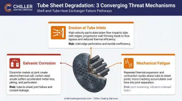
Tube sheets occupy the most demanding position in any STHE, contacting the process fluid on one face and the cooling medium on the other. This dual exposure creates three converging threats:
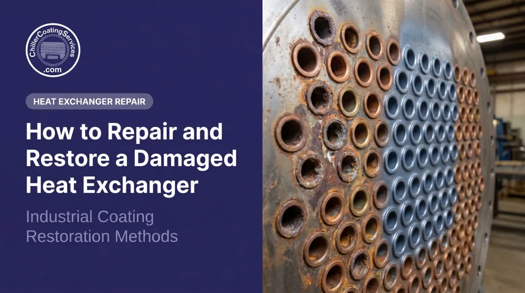
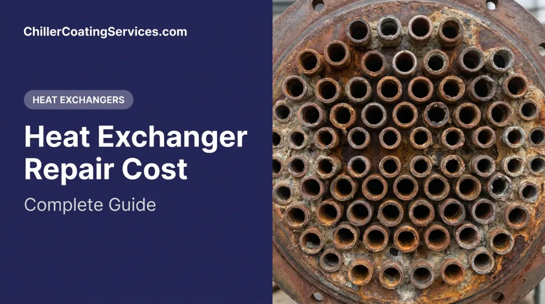
- Galvanic corrosion where dissimilar metals meet at tube-to-tube-sheet joints (carbon steel tube sheets are anodic to more noble stainless or titanium tubes, accelerating localized attack at the joint)
- Erosion at tube inlets from turbulent, high-velocity, or particulate-laden process streams — API 660 requires impingement protection plates (minimum 6 mm thick) extending beyond the nozzle bore where flow conditions warrant
- Mechanical fatigue at tube-to-tube-sheet joints from thermal cycling
Tube sheet integrity is not purely a mechanical concern. Joint failure creates a direct cross-contamination path between process fluid and cooling water, a serious consequence in any high-stakes heat exchanger service.
Protective Tube Sheet Coatings
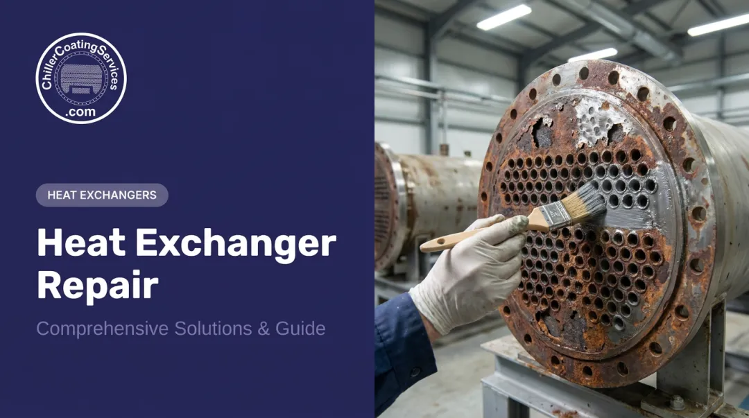
One proven response to tube sheet degradation is professional coating application. Chiller Coating Services applies proprietary 100% solids epoxy coating systems to tube sheets, tube ends, and water boxes in industrial heat exchanger environments.
Their three-step process delivers measurable structural and corrosion protection:
- Deep cleaning to remove deposits, scale, and contaminants
- Contained abrasive blasting to SSPC-SP 5 / NACE No. 1 white metal finish, with reconstruction of severely corroded areas
- 100% solids coating application that creates a non-conductive barrier, interrupting galvanic pathways and resisting erosion
Documented push-out strength gains exceed 1,000 pounds in some cases, reinforcing tube-to-tube-sheet joint integrity where mechanical fatigue or corrosion has compromised the original bond.
Maintenance Best Practices for Refinery STHEs
Inspection Methods and Intervals
Refinery STHEs are pressure vessels and fall under API 510 inspection requirements. Per API 510, internal or on-stream inspection intervals must not exceed the lesser of one-half the calculated remaining life or 10 years; external visual inspection intervals must not exceed 5 years or the internal/on-stream interval, whichever is shorter. Risk-based inspection (RBI) per API RP 581 can adjust these intervals up or down based on damage mechanism likelihood and consequence of failure.
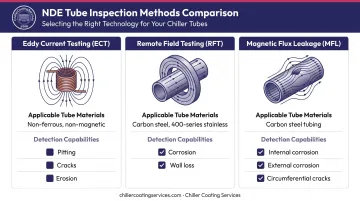
Three NDE methods cover the tube inspection spectrum:
- Eddy current testing (ECT) — for non-ferrous and non-magnetic tubes (copper alloys, Inconel, most stainless steels); detects pitting, cracks, erosion, and metal loss
- Remote field testing (RFT/RFA) — for ferromagnetic tubing (carbon steel, 400-series stainless); detects corrosion, erosion, and wall loss
- Magnetic flux leakage (MFL) — for carbon steel tubing; identifies internal/external corrosion, pitting, and circumferential cracks
Hydrostatic testing per API 660 confirms pressure-boundary integrity but does not substitute for tube-wall NDE.
Tube Sheet Coating as a Long-Term Strategy
NDE finds damage that has already taken hold — coating systems stop it before it starts. Chiller Coating Services' approach follows a three-step process:
- Surface prep: Blast to white metal finish (SSPC-SP 5 equivalent)
- Reconstruction: Rebuild corroded areas before any coating is applied
- Coating application: Apply a 100% solids epoxy system to the full tube sheet face, tube ends, and accessible water box surfaces
The cured coating:
- Creates a non-conductive barrier preventing galvanic attack at dissimilar-metal joints
- Produces a smooth surface that reduces fouling accumulation
- Reduces inlet turbulence, limiting erosion at tube entries
- Withstands long-term immersion and resists a broad range of aggressive chemistries
- Reinforces tube-to-tube-sheet joints, with documented push-out strength gains over 1,000 pounds in some applications
For refineries and petrochemical facilities, coating work is scheduled within planned turnaround windows. Documented service records support API inspection history requirements and facility compliance programs under OSHA PSM and ISO standards.
Industry Standards Governing Refinery STHEs
Two standards form the design and construction backbone for refinery STHEs:
- TEMA Class R — the most stringent TEMA construction class, specified for severe petroleum refining and large-scale chemical processing. Covers shell thickness, baffle design, tube count, and fabrication tolerances within diameter limits of 60 inches and design pressures up to 3,000 psi
- API Standard 660 (Ninth Edition) — governs mechanical design, material selection, fabrication, inspection, testing, and shipment of STHEs for petroleum, petrochemical, and natural gas service. Applies to heaters, condensers, coolers, and reboilers; mandates TEMA Class R construction unless otherwise specified
ASME Section VIII covers the pressure vessel components — shell, channels, heads — for operation above 15 psig.
API Standard 521 requires that tube rupture scenarios be evaluated in relief system design. If a high-pressure tube fails, process fluid can overpressure the low-pressure shell side and connected piping — making overpressure protection sizing one of the most consequential calculations in petroleum service.
Frequently Asked Questions
What types of heat exchangers are used in oil refineries?
Shell and tube heat exchangers dominate refinery operations, with fixed tube sheet, U-tube, and floating head designs serving as reboilers, condensers, preheaters, and coolers. Air-cooled fin-fan exchangers supplement STHEs for certain cooling duties where cooling water is limited or expensive.
How does a shell-and-tube heat exchanger work in an oil refinery?
Process fluid flows through the tube bundle while a second fluid — cooling water or another process stream — flows over the tubes inside the shell, exchanging heat through the tube walls. Baffles on the shell side force cross-flow across the bundle, increasing turbulence and maximizing heat transfer efficiency across demanding refinery conditions.
Why is a shell-and-tube heat exchanger preferred over a double-pipe heat exchanger?
STHEs offer far greater heat transfer surface area, handle much higher thermal loads and pressures, accommodate a wider range of flow rates, and are practical for the continuous, large-scale heat duties found in oil refineries. Double-pipe designs are limited to small capacities and low-duty applications.
What causes tube sheet corrosion in oil refinery heat exchangers?
Tube sheet corrosion is driven by contact with corrosive process fluids (sulfur compounds, naphthenic acids, chlorides), galvanic corrosion from dissimilar metals at tube-to-tube-sheet joints, and erosion from high-velocity turbulent flows at tube inlets. Proper material selection, impingement protection, and protective coatings all mitigate these mechanisms.
How often should shell and tube heat exchangers be inspected in a refinery?
Per API 510, internal or on-stream inspection intervals must not exceed one-half the remaining life or 10 years, with external visual inspections at least every 5 years. Service severity, fouling tendency, and process fluid corrosivity drive the actual frequency, with RBI per API RP 581 used to optimize inspection planning.
What is the 10/13 rule for shell-and-tube heat exchangers?
The 10/13 rule is a rule of thumb: when 10–13% of an exchanger's tubes have been plugged due to failure or degradation, the resulting heat transfer loss and pressure drop increase make continued operation uneconomical. Re-tubing or bundle replacement becomes the more cost-effective decision, though the exact threshold varies by service criticality and exchanger design.